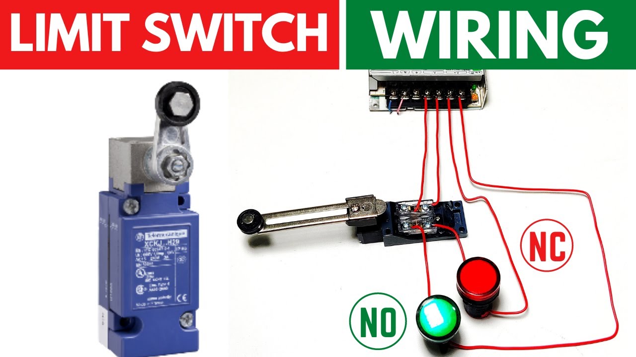
Limit Switch Connection Diagram
Limit switch wiring connection dc load working Fan wiring diagram limit relay switch hvac wire rodgers honeywell control furnace should blower thermostat gas heat presidential valid will Limit switch switches schematic contact arrangement nc normally open common basics form closed instrumentationtools sometimes referred incorporates since both set
Honeywell Fan Limit Switch Wiring Diagram | Wiring Diagram
Actuator switches actuators connection adjustable Cnc grbl limit switch wiring the ultimate solution Limit switch connection/wiring with ac/dc load ii working of limit
How to use an external limit switch kit with a linear actuator
Switches conceptsSwitch limit diagram wiring relay reverse motor polarity direction switches control down wire schematic stop dc electrical two 12v Switches limit switch wiring wireLimit switch wiring cnc grbl.
Basics of limit switchesHoneywell fan limit switch wiring diagram Wiring the limit switchesLimit switch diagram switches board breakout buildyourcnc connecting input pins.
Up down switch wiring diagram
Limit switches – a better way .
.


CNC Grbl Limit Switch Wiring The ultimate solution - YouTube

Honeywell Fan Limit Switch Wiring Diagram | Wiring Diagram

BuildYourCNC - Limit Switch

Basics of Limit switches - Inst Tools

Limit Switches – a better way - Spark Concepts
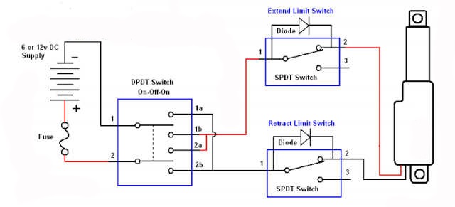
How To Use An External Limit Switch Kit With A Linear Actuator | Actuonix

Up Down Switch Wiring Diagram